IIntroduction
Steps of development of Ceres 1-3 between 1980 and 2003, have frequently brought novelties, but 3-D software (Sirona) surpassed, as a breathtaking innovation, all expectations. Clarity of 3-D model and simple way of its application, as well as much improved quality of restoration of surfaces and margins could bring this system to the universal CAD/CAM manufacture technology for ceramic resto-rations, inlays, veneers, incomplete or complete crowns to the multi-unit bridges. This report includes our experiences obtained at the clinic and in education.
Clarity of 3-D model
Restorative dental
medicine reflects itself in a three-dimensional color ambiance. Cerec
3-D produces three-dimensional quasi-real working model in 12 times
magnification and, thereby as a working support surpasses a physical
model. Preparation is presented accurately with space resolution of 25
micrometers. 3D-model can rotate and move freely, enabling the dentist
control over constructed preparation and restorations from all sides.
Thereby, digital model exceeds plaster model in application as well.
Powerful computer (Pentium 4), current Ceres 3 systems, using 3-D
software collects several optical casts in just a few seconds into a
dental model with the inverse bite. In this way, the normal occlusion
can be considered.1 While the software images of the previous
versions of Ceres 1-3 oriented still two-dimen-sional in technical
drawing,2-4 Cerec 3-D brings the usual world of the dentist
and dental technician immediately on the computer display.5
The clarity of 3-D model itself is fascinating (Figure 1) and provides
the normal dental-medical individual with easy operating the system,
beca-use CAD/CAM experts are not required.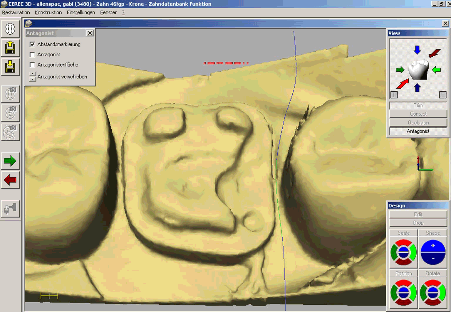
Figure 1. Cerec 3-D model from the data on the display. Preparation oriented to defect with no further annexation in tooth 46 with dividing line for the adjacent tooth implemented on mesial interdental gingiva. On the left monitor margin, a series of buttons, on the left upward, a window for searching the antagonists of different appe-arance; right upward „View“ window where standard appearances of the model e.g.: appearance mesial, distal etc.; along with functions „Trim“, „Contact“, „Occlu-sion“ and antagonist.
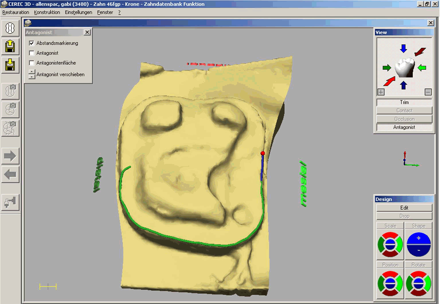
Figure 2. Entering the preparation margin into the defined preparation model (adjacent teeth separated; the course can be controlled from all angles. Automatic margin finder secures the accurate position of the margin line on the preparation margin.

Figure 3. Searching the approximal surface with colored-coding of the contact surface and penetrating the adjacent tooth contact surface, red: >100 mm; yellow: 50-100 mm; green 0-50 mm. Contact strength is customized with design tools in a simple way to the wanted strength. It is taken into consideration that polishing reduces the approximal surface by approximately 50 mm.
Self-explaining operating elements
Selection of standard anatomical appea-rances with arrows for direction, color-coded for mesial, distal etc. provides the orientation of the model in three-dimensional space all the time (Figure 2). By drawing the approximal dividing lines, it is possible to detach the prepared tooth as a cross-section model from the adjacent teeth, i.e. if needed adjacent teeth can be blended out and again, blended in using the trim function (Figure 2). The force of approximal and occlusal (Figure 3 and 4) contacts, can be perfectly fitted using “Contact and Antagonist” for color-coding. Occlusal, that is functional registration is blended-in (Figure 5). In the section image, leaning of the antagonist surface against the chewing crown surface can be continuously passed from medial to distal in the entire occlusal contact area (Figure 5).

Figure 4. Marking too high occlusive contacts after checking with the antagonist surface (virtual contact folia). Buccal cusps and mesiolingual internal cusp side (red: 150 mm; yellow: 100 mm; green 50 mm). To proceeds with corrections, both buccal cusps were reduced in height using “Scale” tool. Fine corrections were performed with „Polish“ and „Shape“. With turning of green toward blue, constructively there is no precontact.
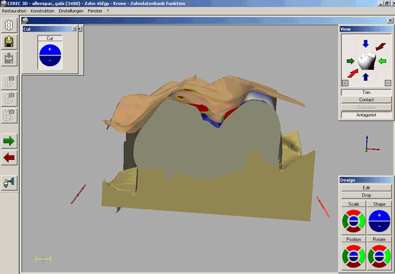
Figure 5. Within the main menu, there is a possibility to choose “Cut” window from the menu “Window”. It enables continuous motion of cross-section images from medial toward distal. Thereby, the relation of antagonist surface and occlusive surface of the newly constructed
Anatomy from the database
Tooth anatomy is put at disposal with 3-D systems with inlays, incomplete and complete crowns from different tooth databases with the help of digitalized forms of teeth. Alternatively, occlusive morphology of the functionally sufficient gold crown (Figure 7) can be copied for a new ceramic crown in “correlation” with optical cast and transferred unchanged into polished ceramic crown. In the following report on this case, we have taken over digital morphology for a new shaping of the crown from the tooth database and the occlusion was shaped taking antagonist into consideration. This system brings the crown from the database directly on the cervical margin of the preparation, and as a suggestion to the structure of teeth. After all, entering the preparation margins supported by Ceres 3-D results in stunning automatic margin search results. Fine adjustment of the crown from the tooth database to the individual morphology and the patient's bite in position, size, shape and in relation to approximal and occlusive contacts, is carried out with “design” tool (Figure 1).
Adjustment of the crown using „Design“
Design, the tool presents the tooth surfaces (mesially, distally, etc.) with rounded segments, coded with the same colors as the standard model appearances (Figure 1). If the crown should be positioned in one of these directions again, („Position“), rotated („Rotate“), as a whole or in parts magnified / reduced i.e. raised / lowered („Scale“), or the surface areas should be changed outward or inward, than it is intuitively possible gradually, if one clicks on the surfaces for activating the direction with visual control over the model. Acquired additive and subtractive way of work of the dentist i.e. dental technician, allows the additional tool (“Drop”) where the material is deposited in drops. In the second function grade, the material can be brought on again for polishing and reduction. This tool is in the first place convenient for smoothing tiny uneven spots or adjusting the contours, and it is much favored by the users. With “Edit” surface applied, elementary outlines, equator, cusps and occlusal carvings can be seen and edited. Also, the initial dots of lines in inlays and incomplete crowns can be edited as well.
Learning Curve
The learning curve in students, dentists and dental technician in relation to previous software versions is much shortened and remains on the same level as with other modern systems. The user is no longer brought on the slippery ice of the CAD working-base strange to him. Using CAD-CAM system is not debased to technical or manual intelligence test which is to be feared from. On the contrary, automatisms of preparation margin finder and following design proposal providing final inlays make the construction with additional adjustments a plaything. Converting the digital construction into clean, exactly fitting ceramic working subjects, sophisticatedly running the form polishing technique on the basis of 3-D system is frequently fascinating (Figure 6). Learning re-sults of one day 3-D intensive courses for dentists and dental technicians enable direct taking up the application of inlay, complete or incomplete crowns in practice and laboratories. The course of propedeutics for students fore-sees 15 hrs for making inlays, and incomplete crowns including adhesive attachment. In the clinical semesters, direct i.e. indirect CAD-CAM restoration (Cerec) is compulsory part of the curriculum, and all works undergo testing.
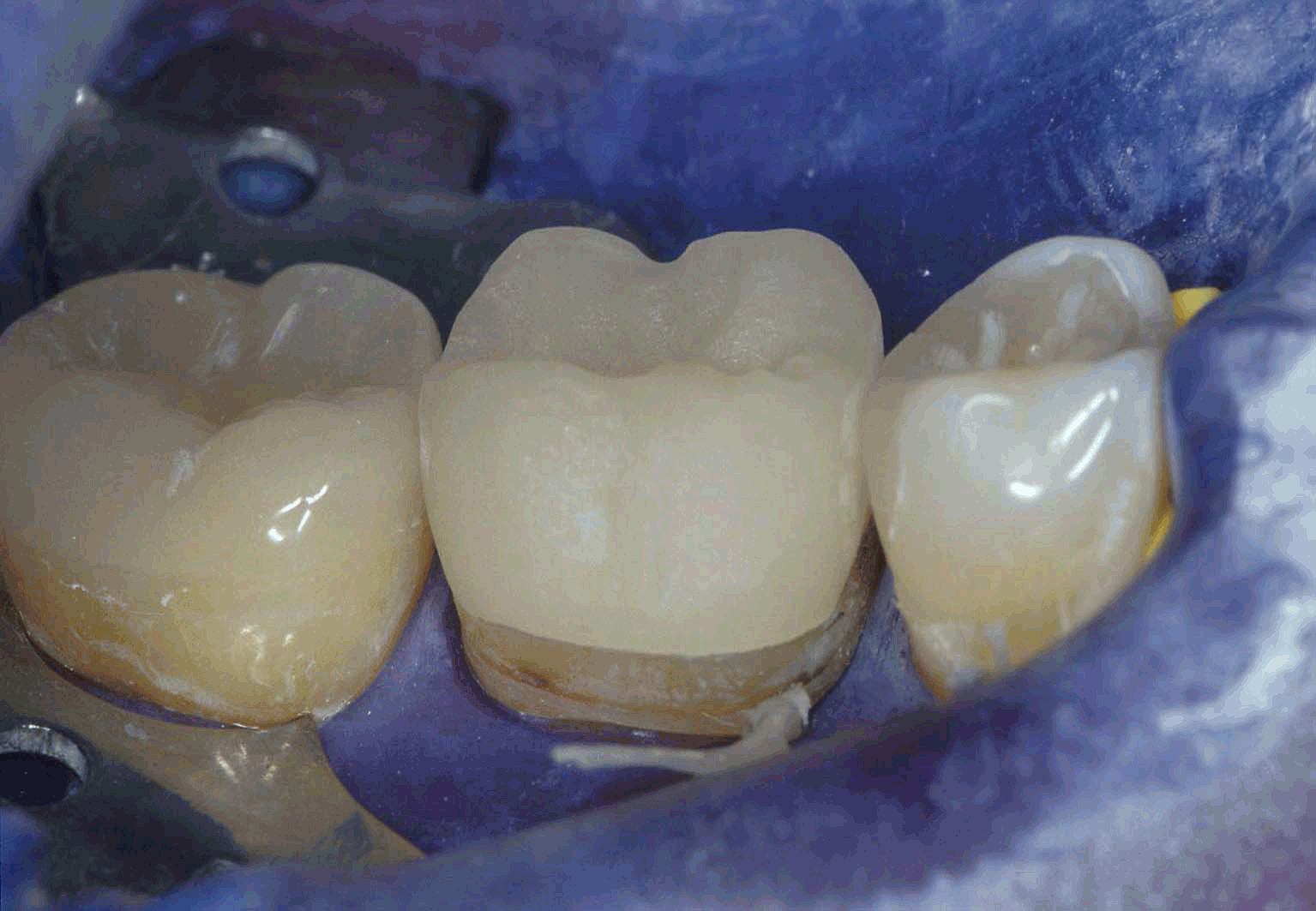
Figure 6. A trial of the crown after polishing the approximal contacts. Perfect crown matching appro-ximally and cervically. Fine quality of the nonpolish grinded ceramic surface. Clear supragingival crown margin. Absolutely dry attachment with cofferdam makes ideal precondition for adhesive atta-chment
Clinical case: Preparation and optical cast
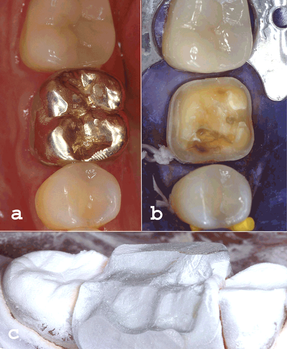
A 57-year-old female patient (G.A.) wanted to replace all gold restorations with ceramic restorations for aesthetic reasons. First, we have ensured medial and distal adjacent gold tooth crowns, (46) (Figure 7a), removed gold crowns and displayed the remained healthy dentin (Figure 7b). The tooth showed positive response to cold test (CO2-spraye). The crown margins were located supragingivally (Figure 7b). We prepared one circular grade 1mm wide. Substance defect in fractured area was not attached (reduced preparation).6 The cons-truction was conducted using “Dental data-base” with centric registration. Centric registra-tion (metal-bite, R-dental) was adjusted approximately with scalpel, in such a way that adjacent teeth were just enough covered and we reponed it with the exact place (Figure 1c). We matted the adjacent teeth with the white powder (Vita), took the optical cast from the registration and supplemented it with mesial and distal image of widening.7 After that, we took off the registration, dispersed the old powder, powdered the preparation and adjacent teeth again, and took each optical cast of the prepa-ration, mesial and distal adjacent teeth.
Figure 7. Original situation (a) shows 4. quadrant. The second premolar and second molar are already provided with chairside Ceres restorations. The gold crown of the first premolar (tooth 46) should be also replaced with ceramic Cerec CAD-CAM crown in one-visit. Situation after the removal of gold crown (b). No bild up is done. Shaped centric bite in situ with powdering of adjacent teeth for taking optical cast (c).
Detailed crown construction
The system included all 6 3-D images (Figure 1). Adjacent teeth were released with “trim” function and brought the cervical margin line in. (Figure 2). We controlled the margin line on 3-D model from all sides and with green arrow “go on” searched the concerned crown form the morphological dental database (Figure 3). With functions “Rotate” and “Position” we attached the crown from the database in the tooth structure. In “Image correction” we shaped the occlusive registration to the cusps impression and main occlusal carvings and in “Antagonist” we selected “Antagonist Surface” (Figure 5). Antagonist surface can be started in contact registration position, but can be brought again in disclusion. In full contact it showed, upon administration of virtual contact folia, too high area in the buccal cusps and mesio-lingual internal cusp side (red: 100m; yellow: 50-100 mm; green: 0-50 mm) (Figure 5,6). To correct them, we reduced both buccal cusps with „Scale“-tool. The fine corrections were perfor-med with „Polishing“ and „Shape“ tools. Con-structively, there is no precontact in passing from green to blue. After 15 minutes of form grinding, we took the crown (Mk II ceramics, color 2 M 1 C; Vita tooth factory) from the grinding chamber and manually grinded the external element.
Adhesive insertion
Working field was completely dried with cofferdam. Approximately, we polished mate crown surfaces polished in fine quality prepolish with flexible disks (Sof-Lex, 3M), experi-mentally mounted the crown and checked the approximal contacts as well as the cervical matching accuracy (Figure 7). We etched the internal surface of the crown with (Ceramics Etch, Vita), silanized (Monobond S, Ivoclar Vivadent) and sealed the tooth with sytac-heliobond-system (Ivoclar Vivadent).8 We filled the crown with Variolink Ultra Base (Variolink Ultra, light establishing component, Ivoclar Vivadent) and established the atta-chment composite with polymerization lamp in duration of 6 min. (Astralis 10, Ivoclar Viva-dent). After removal of cofferdam, we polished composite excesses in the contact area with 40 mm and 8 mm Proxoshape P2 files (Intensively) and polished the contact surface with flexible disks (3M). We marked centric precontacts, if there were any, and polished them. We checked protrusion, mediotrusion and laterotrusion and if needed polished to obtain undisturbed occlusion in statics and dynamics. For reali-stically close 3-D construction the adjustment of interferently free occlusion was reduced to approx. 5 min. We polished the crown surface with flexible disks, occlubrush (Kerr Hawe) and diamond polish paste (Vita) until high radiance was achieved (Figure 8, 9 ).
Discussion
In the past, dental CAD-CAM for making ceramic restorations in the private office or laboratory of a dentist was considered exotic, technically and in result imperfect, rarely used, and in application expensive and complicated by most dentists or technicians. Current picture appears to be different. In January 2003 more than 50% dental offices, in Zurich (12,5%), used Cerec, with increasing tendency after the presentation of Ceres 3-D. The warranty period for works done using these working tools in Switzerland is 10 years. Restoration of a defect with inlays, incomplete crowns2 and later full crowns7,8 in adhesive attachment with compo-site materials applied in our clinic since 1985 was clinically approved.9-14 Cautious conve-rsion and clinical success of ceramic CAD-CAM restorations supported with evidence in several long-term studies in the period of 10 years in private offices of dentists in Germany, Switzerland and internationally.15-23 Huge acceptability of chairside Ceres 3-D application is observable in USA as well.24-28 Considerable interest of dental technicians in Cerec 3D inLab is shown at demonstrations in our office. They make constructive crowns and bridges by using IN-Ceram YZ Cubes Zirconium oxide ceramics of high quality, and blend it with VN 9 ceramics (Vita), but ceramic primary telescopes as well.29 Our experiences in cooperation with dento-techical laboratory include more than 70 lateral bridges and they are very positive. Since the complete inLab 3-D program of dental te-chnique is at disposal, it is considered to be professionally and economically perfect alternative for established dental ways of production. In our opinion Cerec CAD-CAM technology make a decisive step with 3D-image toward general application in restorative dental medicine. An American expressed it in the following way „Dentists will need this revenue-generating technology just to keep up“.28 Acco-rding to our experience, this could refer to our dentists and dental technicians in Germany and Switzerland in the future.
REFERENCE LIST
1. Fritzsche G. Korrelation und Funktion bei Cerec 3D -Was ist neu? Int J Comp Dent 2003; 6: 83-88.
2. Mörmann WH, Brandestini M. Die CEREC Com-puter Reconstruction Inlays, Onlays und Veneers. Berlin: Quintessenz 1989: 75-97.
3. Saliger G. Designing a Cerec crown. In: Mörmann WH, ed. CAD/CIM in esthetic dentistry. Berlin: Quintessence 1996: 427-440.
4. Mörmann WH, Bindl A. Cerec 3 -ein Quanten-sprung bei Computer-Restaurationen -Erste klinische Erfahrungen. Quintessenz, 2000; 51: 157-171.
5. Schneider W: Cerec 3D -Behandeln in einer neuen Dimension. Int J Comp Dent 2003; 6: 57-66.
6. Ender A, Wiedhahn K, Mörmann WH. Die Qua-drantenbehandlung mit der Cerec 3D Software. Int J Comp Dent 2003; 6: 89-94.
7. Mörmann WH, Rathke A, Lüthy H. Der Einfluss von Präparation und Befestigungsmethode auf die Bruchlast vollkera-mischer Computerkronen. Acta Med Dent Helv 1998; 3: 29-35.
8. Bindl A, Mörmann WH. Clinical evaluation of adhesively placed Cerec Endo-Crowns after 2 years -Preliminary results. J Adhesive Dent 1999; 1: 255-265.
9. Mörmann WH. Kompositinlay: Forschungsmodell mit Praxispotential? Quintessenz 1982; 33: 1891-1900.
10. Mörmann WH, Ameye C, Lutz F. Komposit-Inlays: Marginale Adaptation, Randdichtigkeit, Porosität und okklusaler Verschleiss Dtsch Zahnärztl Z 1982; 37: 438-441.
11. Mörmann WH. Keramikinlay -Die Seite-nzahnfüllung der Zukunft. Vortrag am 30.3.1985, Karlsruhe, "25 Jahre Akademie für Zahnärztliche Fortbildung, Karlsruhe". 4. Internationales Quintessenz-Symposium.
12. Mörmann WH, Brandestini M, Ferru A, Lutz F, Krejci I. Marginale Adaptation von adhäsiven Porzellaninlays in vitro. Schweiz Mschr Zahnmed 1985; 95: 1118-1129.
13. Mörmann WH. Innovationen bei ästhetischen Restaurationen im Seitenzahngebiet (Keramik): Compu-tergestützte Systeme. Dtsch Zahnärztl Z 1988; 43: 900-903.
14. Mörmann WH, Brandestini M, Lutz F, Barbakow F. Chairside computer-aided direct ceramic inlays. Quintessence Int 1989; 20: 329-339.
15. Heymann HO, Bayne SC, Sturdevant JR, Wilder AD, Roberson TM. The clinical performance of CAD-CAM-generated ceramic inlays -a four year study. J Am Dent Assoc 1996; 127: 1171-1180.
16. Felden A, Schmalz G, Federlin M, Hiller KA. Re-trospective clinical investigation and survival analysis on ceramic inlays and partial ceramic crowns: results up to 7 years. Clin Oral Invest 1998; 2: 161-167.
17. Sjögren G, Molin M, Van Dijken JWV. A 5-year clinical evaluation of ceramic inlays (Cerec) cemented with a dual cured or chemically cured resin composite lu-ting agent. Acta Odontol Scand 1998; 56: 263-267.
18. Zuellig-Singer R, Bryant RW. Three-year evalu-ation of computer machined ceramic inlays: influence of luting agent. Quintessence Int 1998; 29: 573-582.
19. Martin N, Jedynakiewicz NM. Clinical perfor-mance of Cerec ceramic inlays: a systematic review. Dent Mater 1999; 15: 54-61.
20. Reiss B, Walther W. Clinical long-term results and 10-year Kaplan-Meier survival analysis of Cerec CAD/CAM inlays. Int J Comp Dent 2000; 3: 9-23.
21. Otto T: Computer-Aided Direct Ceramic Resto-rations: A 10-year prospective clinical study of Cerec CAD/CAM inlays and onlays. Int J Prosthodont 2002; 15: 122-128.
22. Bindl A, Mörmann WH. Clinical and SEM evalu-ation of all-ceramic chairside CAD/CAM generated partial crowns up to 5 years. Eur J Oral Sci 2003; 111: 163-169.
23. Posselt AK, Kerschbaum T. Longevity of 2328 chairside CEREC-Inlays and Onlays. Int J Comp Dent 2003; 6: 231-248.
24. Lackey A. Shorten the learning curve: Cerec 3D brings ease of use to chairside CAD/CAM. Contemporary Esthetics and Restorative Practice 2003; 7: No. 9 suppl. 4-6.
25. Goldstein C, Walls R, Voiers W. Achieving high-level esthetics in three-dimensional realism. Conte-mporary Esthetics and Restorative Practice 2003; 7: No. 9 suppl. 7-11.
26. Spaniel J: Technology integration in the next dimension. Contemporary Esthetics and Restorative Practice 2003; 7: No. 9 suppl. 12-14.
27. Simon J, Schmidt B: New CAD/CAM system com-bines simplicity with sophistication. Contemporary Esthe-tics and Restorative Practice 2003; 7: No. 9 suppl. 15-22.
28. Willeford R. Cerec 3D: An investment -not an expense. Contemporary Esthetics and Restorative Practice 2003; 7: No. 9 suppl. 23-24.
- Copyright © 2004 by The Editorial Council of The Acta Stomatologica Naissi